For the September 2014 meeting program SLAARC member Gary Morgan, WA8TJA, presented the process and resources he uses to design printed-circuit boards and have them manufactured for his electronics projects. Bob, WD8AQX, also brought a project he did some years ago in which he converted a CB radio for 10m use.
How_To_Make_Printed_Circuit_Boards (PDF)
Printed_Circuit_Board_Resources (Word doc)
Printed_Circuit_Board_Resources (PDF)
-
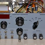
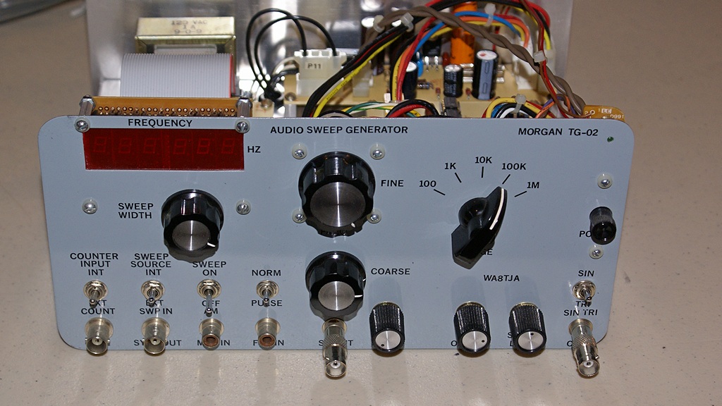
- Front panel of Gary’s Audio Frequency Generator.
-
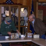
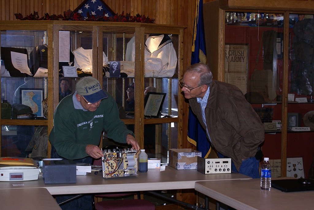
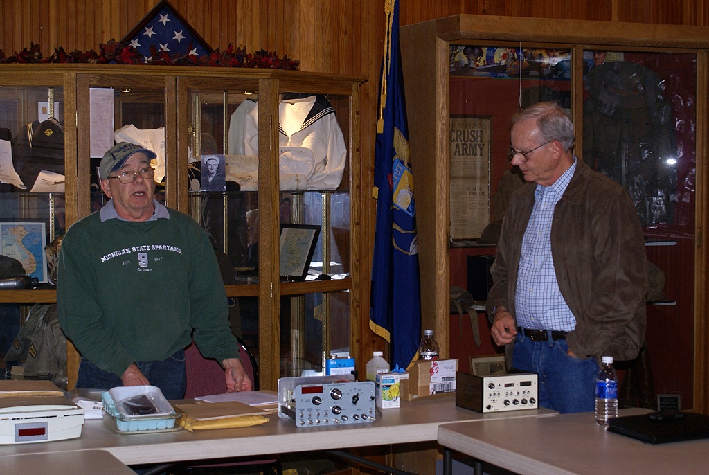
- Gary (L – WA8TJA) and Bob (R – WD8AQX) with their PCB projects.
-
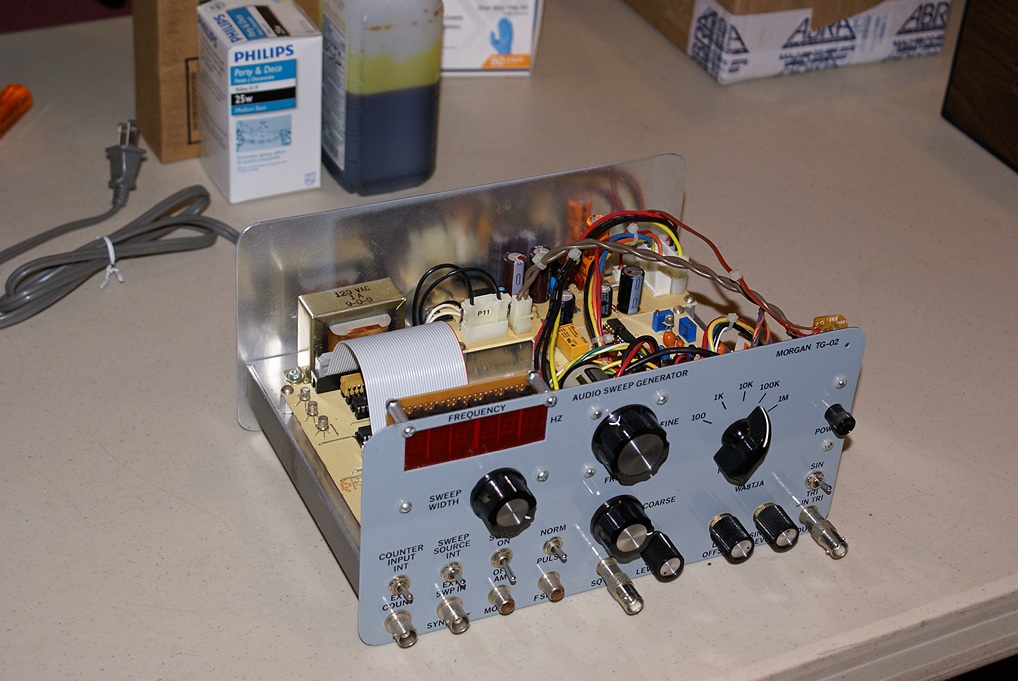
- Gary’s AFG with the top cover removed.
-
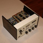
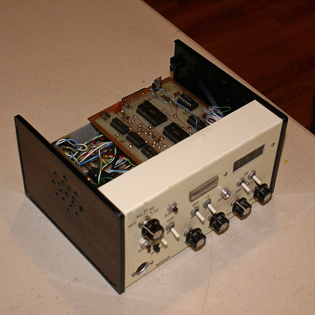
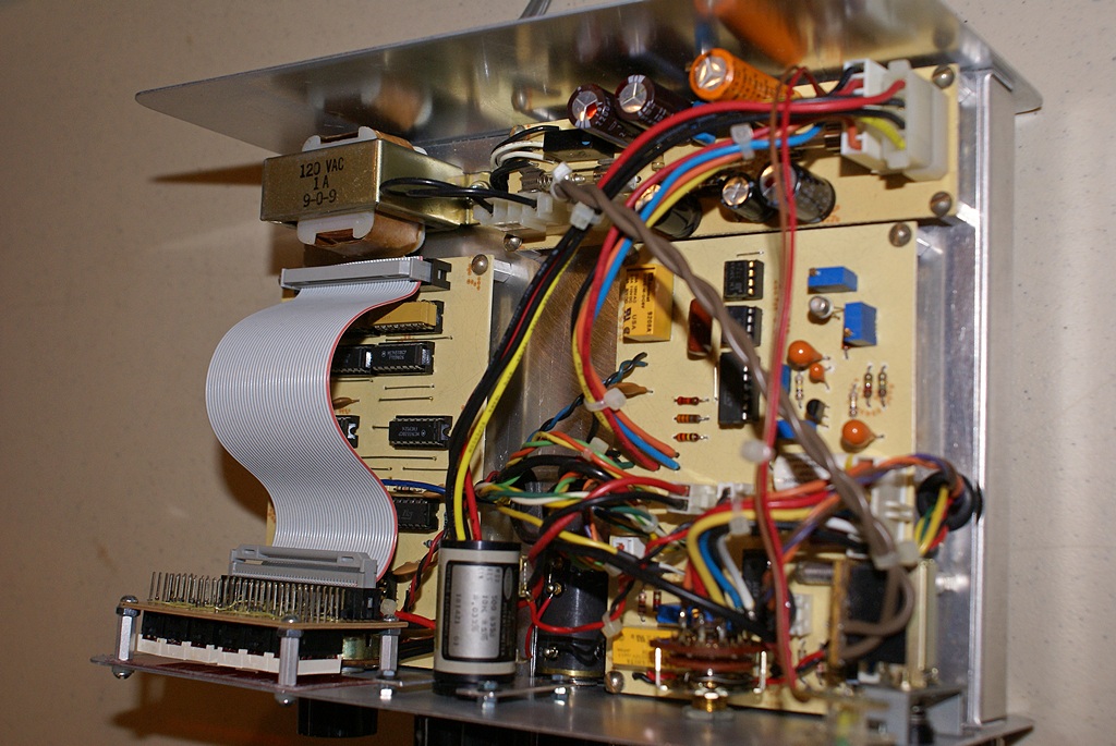
- Bob’s CB radio based 10m rig with top cover removed.
-
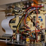
- A view of the printed circuit boards and other construction inside Gary’s AFG.
-
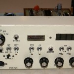
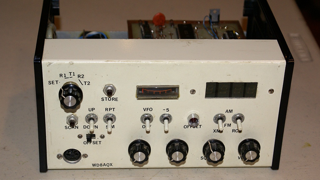
- The front panel of Bob’s 10m CB based rig.
-
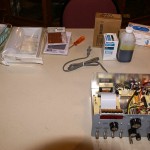
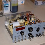
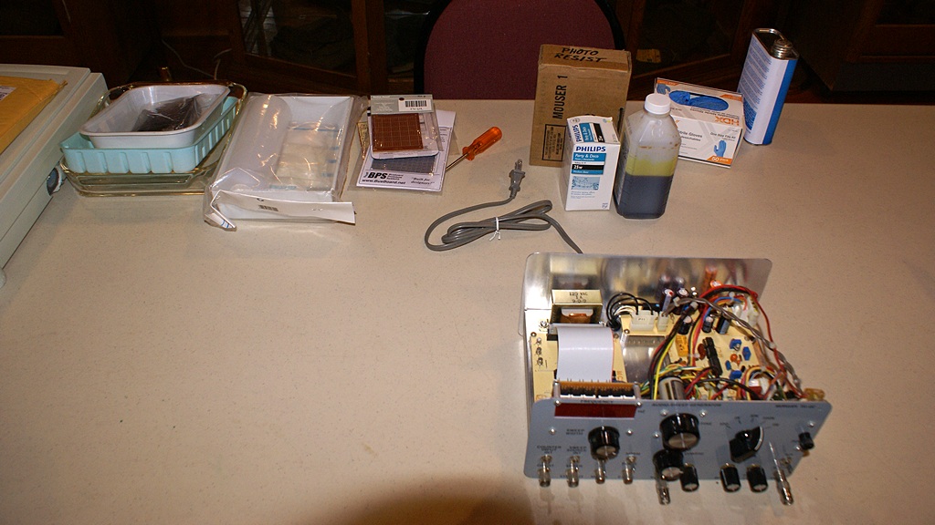
- Gary’s AFG with some of the materials and supplies used to make printed circuit boards.
-
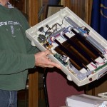
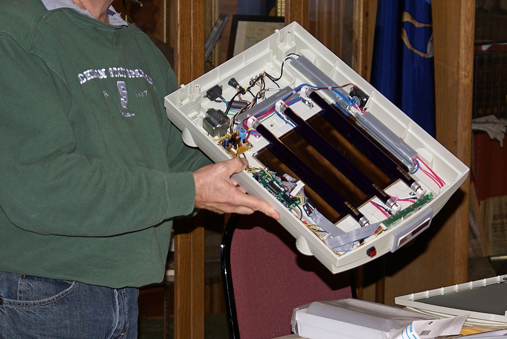
- Gary modified an old flatbed scanner he got from W8RA to make an ultraviolet light exposure table.
-
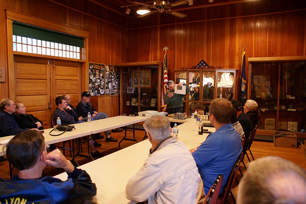
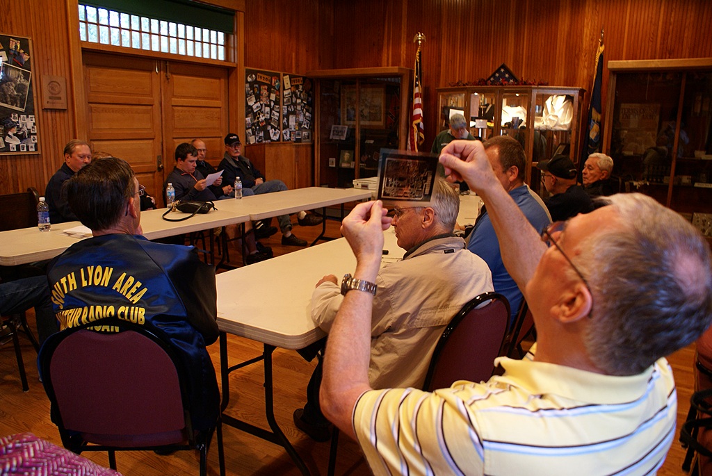
- Gary (WA8TJA) shows fellow SLAARC members one of his PCB negatives (or positives).
-
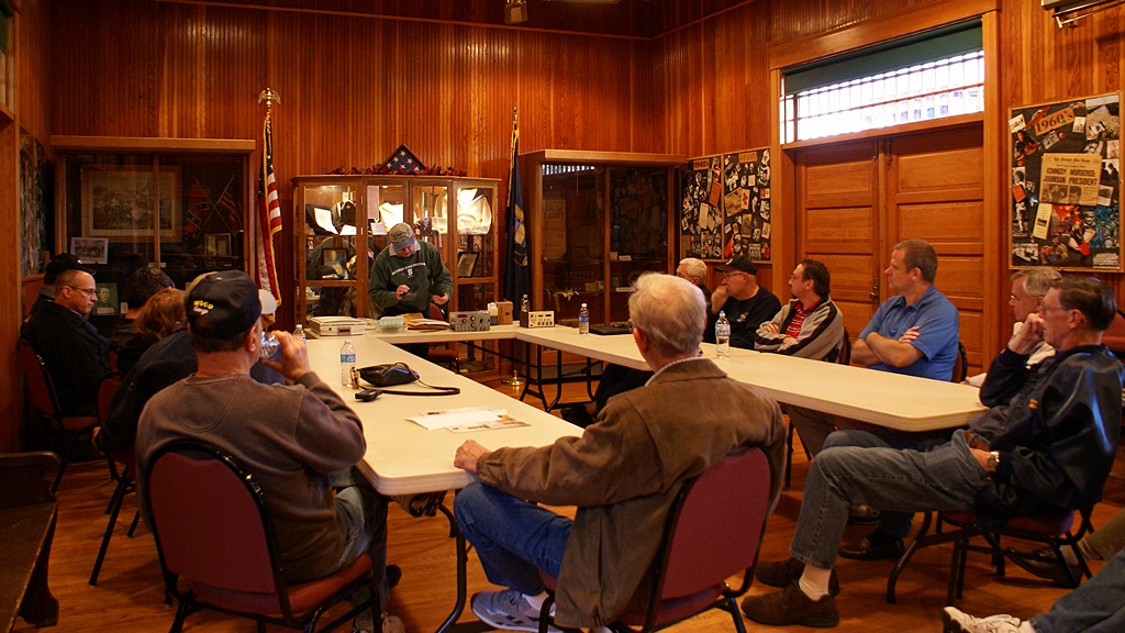
- SLAARC members gathered at the Witch’s Hat Depot in S. Lyon for the monthly meeting and program.
-
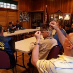
- Mike (W8XH), current SLAARC president, examines a PCB negative (or positive).
-
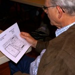
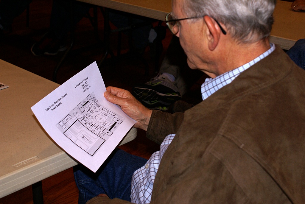
- Bob (WD8AQX) studies a PCB component layout diagram.
-
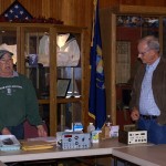
- Gary finishes his presentation and hands the floor to Bob.
-
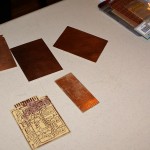
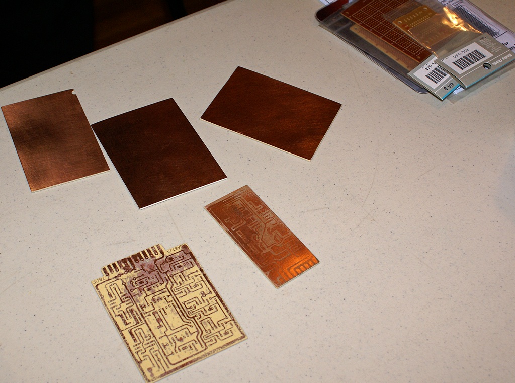
- Examples of copper plated PCB stock and exposed/processed PCBs.
-
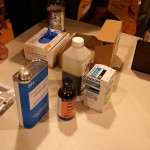
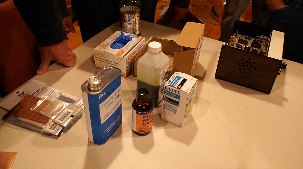
- Some of the chemistry used to make printed circuit boards at home.
-
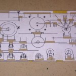
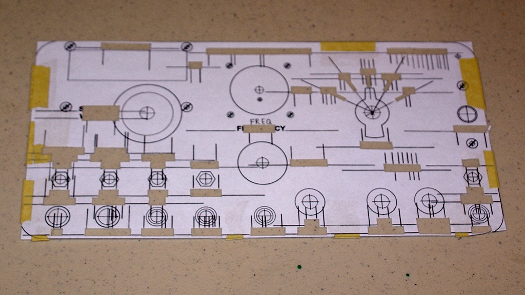
- The front panel template used to locate controls and labels on Gary’s AFG.


You must be logged in to post a comment.